


Views: 0 Author: Site Editor Publish Time: 2026-07-20 Origin: Site


Looking at a specification sheet for a new heating and cooling system often leads to immediate confusion on the job site. You will likely see the term "kW" used twice. It describes both the electricity the system consumes from the grid and the thermal energy it produces for the building. This dual usage of kilowatts creates a significant hurdle during equipment procurement. Misinterpreting these input versus output ratings leads to critical sizing errors. Buyers who confuse electrical draw with heating capacity face serious consequences. You risk purchasing undersized units that provide inadequate climate control during peak winter months. Conversely, oversizing units leads to short-cycling, premature equipment wear, and inflated upfront capital expenditure. We must establish a clear framework for evaluating these systems. You need to differentiate between Input kW, Output kW, and the Coefficient of Performance (COP). Mastering these metrics enables precise system sizing. It allows for accurate operating projections and defensible procurement decisions.
Input kW vs. Output kW: Input kW measures the electrical power required to run the compressor and fans; Output kW measures the actual thermal energy delivered to the space.
The Multiplier Effect: A heat pump does not create heat; it moves it. This allows the Output kW to be significantly higher than the Input kW.
COP as the Ultimate Efficiency Metric: The Coefficient of Performance (Output divided by Input) determines operational efficiency. A COP of 4.0 means 4 kW of thermal energy is generated for every 1 kW of electricity consumed.
Sizing Requires Precision: Relying on nominal capacity without calculating the exact thermal load using the BTU/hr-to-kW conversion formula results in compromised system performance and skewed ROI calculations.
Contractors and facility managers evaluating quotes often struggle to compare different systems side-by-side. Manufacturers use the kilowatt (kW) unit interchangeably for two entirely different physical properties. One represents electrical power drawn from the breaker panel. The other represents thermal energy delivered to the ductwork or hydronic loop. Failing to separate these concepts leads to flawed purchasing decisions and failed inspections.
Input kW defines the maximum or rated electrical draw from your grid. It represents the actual electricity you pay for each month. When we pull permits and size electrical panels, this is the number we look at. Several internal components drive this power consumption.
The compressor requires the most power to pressurize the refrigerant, often accounting for 70% to 80% of the total draw.
The condenser fan forces air across the outdoor coil to reject or absorb heat.
The evaporator fan distributes conditioned air indoors through the duct network.
Control boards, reversing valves, and sensors draw minimal but constant power.
Crankcase heaters draw power during off-cycles in cold weather to keep refrigerant from migrating into the compressor oil.
Input kW dictates your electrical infrastructure requirements. It determines the necessary breaker sizing in your electrical panel. It dictates the wire gauge needed for safe installation to prevent voltage drop and overheating. It also impacts your overall panel capacity. You must ensure your building can handle this electrical load before installation. If a unit has an Input kW of 5.0 kW at 240 volts, it will draw roughly 21 amps continuously, requiring at least a 30-amp dedicated circuit and 10 AWG copper wire.
Output kW measures the volume of thermal energy transferred. It represents the heat moved into or out of the building envelope. This metric dictates whether the system can meet your peak heating or cooling load. If your building loses 15 kW of heat per hour at -10°C, you need an Output kW of at least 15 kW at that specific outdoor temperature to maintain indoor comfort.
Output kW is what you feel at the supply registers. It is the physical heat energy that warms the room. When we perform a Manual J load calculation, the final number we generate is the required Output kW. We then match that requirement against the manufacturer's extended performance data to select the right chassis size.
A heat pump operates on the refrigeration cycle. It does not generate heat by burning fuel or using electrical resistance. Instead, it absorbs ambient heat from the outside air or ground. It then compresses that heat to a higher temperature and transfers it indoors. Because it only moves existing heat, the Output kW is consistently higher than the Input kW. The electricity merely powers the transfer mechanism.
Think of it like a water pump. A small electric motor can move thousands of gallons of water uphill. The motor isn't creating the water; it's just doing the work to move it. Similarly, the compressor does the work to move thermal energy from a low-temperature environment to a high-temperature environment.
Evaluating efficiency metrics helps determine long-term operating viability. The Coefficient of Performance (COP) bridges the gap between electrical input and thermal output. It is the ultimate measure of how well the refrigeration cycle is performing under specific conditions.
The standard formula for calculating COP is straightforward. You divide the Heat Output (kW) by the Electrical Power Input (kW). We use this calculation constantly in the field to verify if a system is operating within manufacturer specifications during commissioning.
Measure the actual electrical draw at the disconnect switch using a true RMS clamp meter. Convert amps and volts to Input kW.
Measure the supply and return air temperatures, along with the airflow volume (CFM), to calculate the actual Output kW.
Divide the Output kW by the Input kW.
Consider a standard performance calculation. A system delivers 12 kW of thermal output. It consumes 3 kW of electrical input. You divide 12 by 3. This results in a COP of 4.0. You get four units of heat for every one unit of electricity.
Now consider a high-efficiency performance calculation. A premium variable-speed system delivers 8 kW of thermal output. It consumes only 1.5 kW of electrical input. You divide 8 by 1.5. This results in a COP of 5.33. This demonstrates the wide range of performance available in modern equipment.
Direct electric resistance heaters face a strict thermodynamic limit. Baseboard heaters, electric furnaces, or the backup heat strips inside an air handler convert electricity directly into heat. Their COP is strictly capped at 1.0. This represents 100% efficiency. One kilowatt of electricity yields exactly one kilowatt of thermal energy. They cannot exceed this ratio.
Contrast this with the multiplier effect of modern refrigeration cycles. Modern systems deliver three to five times the thermal energy per kilowatt of electrical input. They bypass the 1.0 limit by harvesting free environmental heat. This fundamental difference makes them vastly more efficient than resistance heating. When a system drops to a COP of 1.0, it is no better than a cheap space heater.
Heating Technology | Typical Input kW | Typical Output kW | Average COP |
|---|---|---|---|
Electric Baseboard | 5.0 kW | 5.0 kW | 1.0 |
Standard Air-Source | 2.5 kW | 7.5 kW | 3.0 |
Cold-Climate Air-Source | 2.0 kW | 8.0 kW | 4.0 |
Ground-Source (Geothermal) | 1.5 kW | 7.5 kW | 5.0 |
Understanding baseline expectations helps you evaluate manufacturer claims. You need to know what is actually achievable in the field versus what is printed in a glossy brochure.
A COP of 3.0 represents standard, acceptable performance for entry-level equipment.
A COP of 4.0 or higher is considered good and represents mid-tier to high-tier inverter systems.
A COP of 5.0 or higher is exceptional and usually reserved for ground-source systems or air-source systems operating in very mild weather.
Air-source systems typically operate in the 3.0 to 4.0 range depending on outdoor temperatures. Geothermal-source baselines are generally higher. Ground temperatures remain stable year-round, allowing geothermal systems to frequently achieve COPs of 4.5 to 5.5 regardless of the blizzard happening above ground.
Nominal COP has a major limitation. It is measured at a specific, idealized laboratory temperature, usually 7°C (45°F) outdoors and 20°C (68°F) indoors. Real-world conditions fluctuate constantly. To address this, the industry uses dynamic efficiency metrics.
The Seasonal Coefficient of Performance (SCOP) measures efficiency across an entire heating season. It accounts for varying outdoor temperatures by blending performance data from multiple temperature bins. The Heating Seasonal Performance Factor (HSPF) serves a similar purpose in North American markets, though it mixes BTUs and watt-hours. These metrics provide more accurate, climate-adjusted evaluation dimensions for your long-term operating projections.
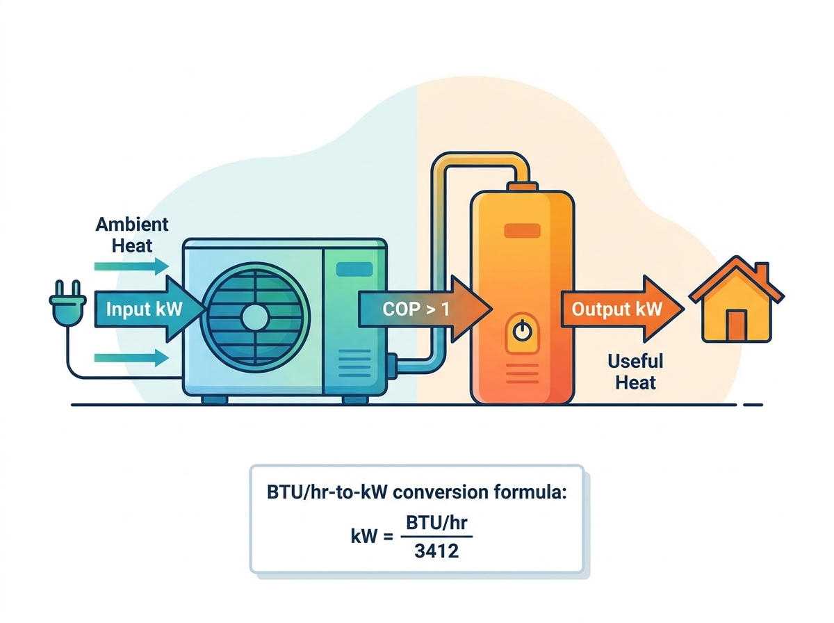
Bridging legacy imperial measurements with modern metric specifications ensures accurate load matching. You must translate older metrics to evaluate modern equipment properly. When replacing a 20-year-old rooftop unit, you have to convert the old nameplate data into modern standards.
North American markets still rely heavily on British Thermal Units (BTUs) or "Tons" for HVAC sizing. However, global manufacturers specify output in kW. This discrepancy requires careful translation to avoid sizing errors. A "Ton" of cooling capacity originates from the amount of heat required to melt one ton of ice over 24 hours. It is an archaic measurement, but it remains deeply entrenched in the trade.
You must use the BTU/hr-to-kW conversion formula to evaluate quotes accurately. The exact mathematical constant is 1 kW = 3,412.14 BTU/hr. We use this constant daily when cross-referencing engineering plans with equipment submittals.
Here is the step-by-step conversion process. Suppose your building requires 48,000 BTU/hr of heating based on the load calculation.
Identify the total BTU/hr requirement (e.g., 48,000).
Divide that number by the constant 3,412.14.
The result is 14.06. You need an Output requirement of approximately 14.1 kW.
Check the manufacturer's extended data to find a unit that delivers 14.1 kW at your specific winter design temperature.
You also need the secondary conversion for HVAC "Tons". One Ton equals 12,000 BTU/hr. This translates to approximately 3.5 kW of capacity.
HVAC Tons | BTU/hr | Equivalent Output kW |
|---|---|---|
1.0 Ton | 12,000 | 3.51 kW |
2.0 Tons | 24,000 | 7.03 kW |
3.0 Tons | 36,000 | 10.55 kW |
4.0 Tons | 48,000 | 14.06 kW |
5.0 Tons | 60,000 | 17.58 kW |
Geothermal capacity calculation differs significantly from air-source systems. It relies on ground heat exchange rather than ambient air. The metric of thermal output is expressed per unit length of borehole. This is typically measured in Watts per meter of borehole depth (W/m). Soil conductivity, moisture content, and rock formations dictate this value.
Undersizing borehole lengths creates severe problems. It limits the peak thermal energy extraction. Over extended heating cycles, the ground temperature drops toward absolute zero because the system extracts heat faster than the earth can replenish it. This artificially depresses the COP and can literally freeze the ground solid around the pipes. Proper borehole sizing is mandatory for sustained geothermal efficiency.
Accurate sizing prevents operational failures. Undersizing results in the inability to maintain setpoints during design-temperature days. The system will run continuously without satisfying the thermostat. It will force reliance on expensive auxiliary backup heat strips. This destroys your efficiency gains and spikes your electrical consumption.
Oversizing carries equally severe risks. It causes high initial capital expenditure for equipment you do not need. The unit will short-cycle, turning on and off rapidly because it satisfies the thermostat too quickly. This degrades compressor lifespan by preventing proper oil return. It also results in poor latent heat removal, ruining humidity control during cooling mode and leaving the building feeling cold and clammy.
Specific hardware features impact the relationship between Input kW, Output kW, and overall COP. You must evaluate these features carefully when reviewing submittals from contractors.
Variable-speed inverter technology modulates Input kW to precisely match the required Output kW. It speeds up or slows down based on real-time demand. This maintains a higher average COP compared to on/off single-stage units. Single-stage units blast at 100% capacity until the thermostat is satisfied, then shut off completely. This creates massive temperature swings and high inrush currents.
Inverters provide smooth, continuous, and efficient operation. They can ramp down to 20% or 30% capacity during mild weather, sipping electricity while maintaining perfect indoor temperatures. This modulation is the key to achieving high SCOP ratings.
You must understand a critical trade-off in air-source systems. As ambient outdoor temperatures drop, Output kW decreases because there is less heat available in the air. Simultaneously, Input kW increases as the compressor works harder and runs at higher RPMs to extract that scarce heat. This lowers the COP significantly.
Do not rely solely on the nominal 7°C (45°F) rating. Evaluate the "Capacity Maintenance" charts at sub-zero temperatures. Look at performance data at -15°C (5°F) or even -25°C (-13°F). Ensure the system retains enough Output kW to heat your building during the coldest days of the year without relying heavily on resistance backup.
You must address the physical and infrastructural barriers to achieving the stated COP and capacity. Theoretical efficiency means nothing if the installation is flawed. Field conditions dictate actual performance.
Your facility's existing electrical panel may not support the new equipment. The Input kW and starting amps (Locked Rotor Amps, or LRA) might exceed your capacity. This is a major implementation risk, especially in older buildings with 100-amp services.
Conduct a thorough load calculation on the electrical panel prior to procurement. Consider installing soft-start kits to reduce the initial surge of starting amps by up to 60%. If necessary, budget for a complete panel upgrade to a 200-amp or 400-amp service to safely handle the continuous load.
Existing ductwork or hydronic radiators are often sized for high-temperature fossil fuel systems. A gas furnace delivers air at 55°C (130°F). A modern system might deliver air at 35°C (95°F). They cannot adequately distribute the lower-temperature Output kW of modern equipment. This mismatch ruins system performance and causes comfort complaints.
You must upsize emitters like radiators to increase the surface area for heat transfer. For forced-air systems, verify duct static pressure tolerances before installation. Ensure the blowers can move enough air (CFM) to compensate for the lower supply temperatures without exceeding the static pressure limits of the ductwork.
Over-reliance on marketing brochures is dangerous. Brochures often state theoretical maximum COPs achieved under impossible laboratory conditions. They highlight the best-case scenario and bury the cold-weather performance data in the fine print.
Cross-reference manufacturer specifications with independent, third-party testing databases. Use the AHRI directory in North America or Eurovent in Europe. These databases verify certified performance data. They protect you from exaggerated marketing claims and ensure you get the Output kW you paid for.
Realizing the true value of modern HVAC equipment requires a strict differentiation between electrical input and thermal output during the specification phase. You must look past the marketing terminology and focus on the hard engineering data. Follow these concrete steps to ensure a successful installation.
Commission a professional Manual J heat load calculation to determine your exact Output kW requirements for every room.
Audit your current electrical panel capacity to ensure it can handle the required Input kW and starting amps without tripping the main breaker.
Request extended performance data sheets at design-day temperatures from prospective contractors to verify cold-climate capacity retention.
Upsize your ductwork or hydronic emitters to handle the lower supply temperatures required for high-efficiency operation.
A: A COP of 3.0 is considered standard performance for entry-level units. A COP of 4.0 or higher is good, representing mid-tier inverter systems. Systems achieving a COP of 5.0 or above are considered exceptional and are typically ground-source or highly advanced air-source units operating in mild conditions.
A: Divide your total BTU/hr requirement by the constant 3,412.14 to find the equivalent kW. For example, a 24,000 BTU/hr load divided by 3,412.14 equals approximately 7.03 kW of required output capacity. This ensures accurate equipment matching.
A: One number represents Input kW, which is the electrical power the unit consumes from your breaker panel. The other represents Output kW, which is the actual thermal heating or cooling capacity delivered to your ductwork or hydronic loop.
A: Yes. As outdoor temperatures drop, there is less ambient heat available. The compressor must work harder, run at higher RPMs, and operate longer to extract heat, increasing electrical consumption (Input kW) while thermal output (Output kW) decreases.
A: COP measures efficiency at a specific, idealized laboratory temperature. SCOP (Seasonal Coefficient of Performance) and HSPF (Heating Seasonal Performance Factor) measure average efficiency across an entire heating season, accounting for real-world climate fluctuations and temperature bins.
A: It does not create energy; it moves existing ambient heat from the outside environment indoors. Because moving heat requires significantly less electricity than generating it via resistance, the thermal output is much greater than the electrical input.


