


Views: 0 Author: Site Editor Publish Time: 2026-08-28 Origin: Site


Homeowners and facility managers upgrading to a hydronic heating system often face conflicting advice regarding system architecture. Some installers insist a buffer tank is a mandatory component to protect the equipment. Others claim it destroys system efficiency and inflates installation complexity. This contradiction leaves property owners unsure of how to proceed with their mechanical upgrades.
The stakes of this design choice are high. Omitting a buffer tank when the system physically requires one leads to catastrophic short cycling, high-pressure lockouts, and premature compressor failure. Conversely, installing an unnecessary or poorly configured buffer tank degrades the Coefficient of Performance (COP). A degraded COP forces the system to consume more electricity to deliver the same amount of heat, inflating energy bills and negating the financial benefits of the mechanical upgrade.
This article provides an objective, evidence-based framework for evaluating whether your specific system architecture requires a buffer tank. You will learn how to assess installer quotes, understand the hydronic mechanics at play, and balance system longevity with peak operational efficiency. We will break down flow rates, emitter volumes, and zoning strategies so you can challenge poor designs.
Volume and Zoning Dictate Necessity: A buffer tank is primarily required if your system’s smallest heating zone cannot provide the minimum water volume necessary to sustain a 10-to-15-minute compressor run time.
Flow Rate Decoupling: Buffer tanks act as hydronic separators, resolving conflicts between the high flow rate required by the heat pump and the variable flow rates demanded by the building's heat emitters.
The Efficiency Trade-off: While buffer tanks protect the compressor, a poorly piped configuration (e.g., standard 4-pipe setups without proper temperature management) can lower the delivery temperature, forcing the unit to work harder and reducing overall COP.
Inverter Technology Changes the Rules: Modern modulating (inverter-driven) units can often operate efficiently without a buffer tank in open-loop systems, provided there is adequate thermal mass in the heat emitters (like underfloor heating).
A buffer tank acts as a hydraulic bridge between two independent water circuits. The primary circuit consists of the heat pump and its dedicated circulation pump. The secondary circuit comprises the building's heat emitters, such as radiators or underfloor heating loops, driven by a separate circulation pump.
These two circuits rarely demand the same flow rate. The primary unit requires a high, constant flow rate to transfer thermal energy efficiently across its internal plate heat exchanger. For example, a 12kW unit might require a strict 35 liters per minute to maintain a 5-degree Delta T (ΔT). Meanwhile, the secondary circuit experiences highly variable flow rates. As thermostatic radiator valves (TRVs) open and close based on individual room temperatures, the secondary flow rate fluctuates wildly.
A buffer tank decouples these circuits. It allows the primary pump to maintain its required 35 liters per minute flow rate even if the secondary circuit restricts flow down to 10 liters per minute due to satisfied room thermostats. The excess primary flow simply bypasses the secondary circuit by circulating through the body of the tank. This prevents flow rate bottlenecks, stops the primary circulation pump from dead-heading, and protects the system from high-pressure faults.
Air-to-water units extract thermal energy from outdoor air. During winter, moisture in the air freezes on the outdoor evaporator coil. This ice buildup restricts airflow across the aluminum fins and severely reduces heat transfer efficiency. To remove this ice, the system initiates a defrost cycle by temporarily reversing its refrigeration cycle. It essentially becomes an air conditioner, extracting thermal energy from the indoor heating circuit and sending it to the outdoor coil to melt the ice.
If the system lacks sufficient water volume, this sudden extraction of thermal energy causes a rapid drop in the circulating water temperature. If you only have 30 liters of water in the entire pipe network, a 4-minute defrost cycle can strip all the heat from that water. This leads to a noticeable drop in indoor room temperatures. Worse, it can cause the system to fault out if the return water temperature falls below the manufacturer's minimum threshold (often around 15°C). A buffer tank provides a reservoir of stored thermal energy. It allows the unit to complete its defrost cycle by drawing heat from the tank's volume rather than pulling heat directly from the building's emitters.
Short cycling occurs when a heating system turns on and off rapidly because it satisfies the building's heat demand faster than it can modulate its output. Every time a compressor starts, it experiences mechanical stress. It draws a massive surge of electrical current known as locked rotor amps (LRA). Furthermore, the internal lubricating oil needs time to circulate properly. Frequent starting and stopping accelerate mechanical wear and tear, drastically reducing the lifespan of the compressor bearings and scroll plates.
A buffer tank introduces additional thermal mass into the hydronic circuit. This extra water volume absorbs the excess thermal output. Instead of heating a tiny volume of water in two minutes and shutting down, the compressor is forced to run for longer, sustained periods to heat the entire tank. Longer run cycles reduce mechanical fatigue, improve lubrication distribution within the compressor shell, and optimize electrical consumption by minimizing startup spikes.
Industry skepticism surrounding buffer tanks stems from poor implementation in the field. In many markets, over-buffered systems are a leading cause of underperformance. The issue lies in the thermodynamics of temperature drop across a poorly configured tank. In a standard four-pipe configuration, hot supply water from the primary unit enters the tank and mixes with cooler return water returning from the heating circuit.
This internal mixing effect lowers the temperature of the water leaving the tank to supply the radiators. If the primary unit supplies 45°C water into the tank, but it mixes with 35°C return water, the water exiting the tank to the radiators might only be 40°C. To achieve the desired 45°C radiator temperature, the primary unit must output water at 50°C to compensate for the mixing loss.
Because the efficiency of a heat pump decreases by roughly 2.5% for every single degree the flow temperature is raised, this forced temperature elevation directly degrades the COP. A 5-degree penalty across a poorly piped buffer tank results in a 12.5% loss in overall system efficiency.
Older fixed-speed compressors operated on a strict on/off basis. They delivered 100% capacity whenever active. These systems strictly required buffer tanks to absorb the massive influx of thermal energy and prevent rapid cycling. Modern inverter-driven units operate differently. They use variable frequency drives to modulate their compressor speed, matching the real-time heat load of the building.
However, modulation has physical limits. Even the most advanced inverter-driven compressors can only modulate down to roughly 20% to 30% of their maximum capacity. A 16kW unit might only be able to modulate down to 4kW. If the building's heat load drops below this 4kW minimum modulation threshold, the unit will still short cycle unless there is sufficient water volume to absorb the excess energy.
Highly variable weather during the spring and autumn shoulder seasons presents the highest risk for short cycling. During these periods, outdoor temperatures are mild (e.g., 12°C to 15°C), and the building requires very little thermal energy to maintain comfort. The actual heat loss of the house might only be 1.5kW.
If the inverter compressor can only modulate down to 4kW, it is producing 2.5kW more heat than the house needs. Without adequate thermal mass in the system, the unit will quickly heat the small volume of circulating water, shut down, and restart minutes later as the water cools. A buffer tank mitigates this by providing a larger volume of water to heat, extending the run time even when the building's actual heat demand is minimal.
Some installers quote buffer tanks as a default safety net. Installing a large buffer tank with secondary circulation pumps eliminates the need to perform complex pipe sizing calculations, flow rate assessments, and room-by-room heat loss calculations. The tank acts as a hydraulic band-aid. It ensures the primary unit operates without flow faults regardless of how poorly the secondary circuit is designed or how restrictive the existing pipework is.
This practice shifts the cost and efficiency penalty onto the end-user. The property owner pays for unnecessary hardware, additional circulation pumps, and suffers the long-term financial impact of a degraded COP due to tank mixing. A properly engineered system requires the installer to do the math, not just throw a tank at the problem.
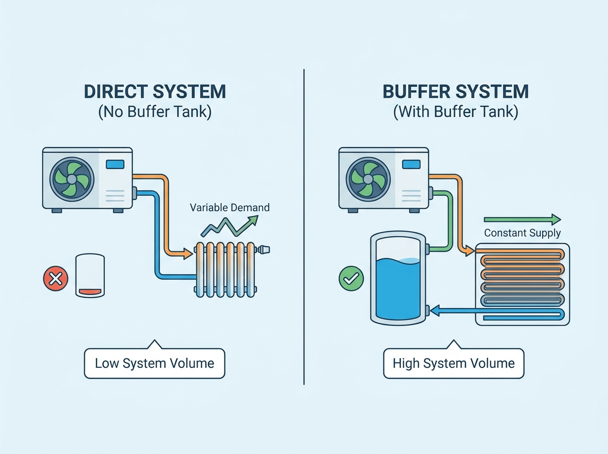
The physical water volume held within the heat emitters dictates the system's thermal inertia. Traditional steel panel radiators hold very little water compared to underfloor heating systems. A standard residential radiator circuit utilizing 15mm copper pipework might only contain 30 to 50 liters of water in total across the entire house.
This low volume is insufficient to sustain a compressor run cycle or provide the thermal energy required for a defrost cycle. When retrofitting a modern primary heating unit onto an existing low-volume radiator circuit, a buffer tank is almost always required to meet the manufacturer's minimum system volume thresholds. Without it, the system will lock out on low return temperatures during the first winter freeze.
Highly zoned properties present significant hydraulic challenges. If a system utilizes multiple TRVs, smart radiator valves, or independent motorized zone valves, the active water volume fluctuates constantly. If several zones close simultaneously because those rooms reached their target temperature, the available water volume and flow path shrink drastically.
Operating a high-flow primary unit into a restricted, micro-zoned secondary circuit causes rapid pressure spikes. The primary circulation pump will struggle against the high dynamic head pressure, leading to flow errors and lockouts. A buffer tank is critical in these scenarios to maintain minimum flow rates across the primary heat exchanger, regardless of how many secondary zones close.
A mathematical mismatch between primary and secondary flow rates necessitates hydronic separation. For example, a specific primary unit might require a minimum flow rate of 30 liters per minute to transfer heat efficiently. However, the existing microbore pipework (e.g., 10mm or 8mm plastic pipe) in the radiator circuit might only physically accommodate 12 liters per minute without causing severe hydraulic noise and pipe erosion.
Pushing 30 liters per minute through restrictive pipework is physically impossible without damaging the system and burning out the circulation pump. A buffer tank resolves this by allowing the primary pump to circulate 30 liters per minute through the tank, while the secondary pump circulates 12 liters per minute through the restrictive radiators.
Bivalent systems utilize multiple heat sources to meet the building's thermal demands. Integrating a primary electric unit with a secondary gas boiler, solar thermal array, or wood-burning stove requires a central thermal hub to manage the different energy inputs and varying flow temperatures.
A buffer tank serves as this central hub. It receives thermal energy from all active sources, mixes it, and distributes it to the heating circuits. Attempting to pipe multiple heat sources directly into a single heating circuit without a buffer tank causes severe hydraulic conflicts, reverse flow issues, and control logic failures.
An open-loop design eliminates the need for hydronic separation. In this configuration, a specific percentage of the heating circuit remains permanently open, without TRVs or zone valves. The temperature of this open zone is managed by a central, weather-compensated curve rather than individual room thermostats.
Leaving a large section of the system open guarantees a constant minimum flow rate and a fixed minimum water volume. If this guaranteed volume exceeds the manufacturer's requirements for run times and defrost cycles, the buffer tank can be safely omitted. This maximizes system efficiency by allowing direct flow from the primary unit to the emitters without any temperature degradation.
Extensive underfloor heating (UFH) embedded in a concrete screed acts as a massive thermal battery. The concrete absorbs and stores vast amounts of thermal energy. The pipework itself holds a significant volume of water. A standard 100-square-meter UFH installation using 16mm pipe at 150mm centers holds over 110 liters of water.
This combination of high water volume and massive thermal inertia renders a separate buffer tank redundant. The primary unit can modulate its output directly into the concrete slab. The floor itself prevents short cycling and provides more than enough stored energy for defrost cycles.
When a system lacks sufficient water volume but does not require flow rate decoupling, a volumizer presents a high-efficiency compromise. A volumizer is a small, inline tank (typically 20 to 50 liters) installed on the return pipework just before the water enters the primary unit.
Unlike a standard buffer tank, a volumizer does not separate the primary and secondary circuits. It simply adds raw water volume to the existing circuit. This provides the necessary thermal mass for defrost cycles and run-time management without the risk of temperature mixing, thereby preserving the system's COP.
Proper sizing requires a formulaic approach based on the primary unit's minimum modulated output capacity. The calculation must evaluate the smallest single heating zone that can remain open independently. If the system allows a single bedroom radiator to operate while all other zones are closed, that single radiator and its associated pipework represent the minimum system volume.
The water volume in that smallest zone must be capable of absorbing the primary unit's minimum output for at least 10 to 15 minutes without exceeding the target flow temperature. If the smallest zone cannot sustain a 15-minute continuous run time, additional volume must be added via an open loop, a volumizer, or a buffer tank.
The physical piping strategy dictates the system's efficiency and hydraulic stability. Each configuration carries distinct implementation realities.
4-Pipe Configuration: This setup provides absolute hydraulic separation. Two pipes connect the primary unit to the tank, and two pipes connect the tank to the emitters. It offers maximum flow protection but carries the highest risk of temperature degradation and efficiency loss due to internal mixing.
2-Pipe Configuration: This is a direct connection strategy without a buffer tank. It offers maximum efficiency and zero temperature degradation. However, it requires precise system design, guaranteed open loops, and high-volume emitters to prevent flow faults.
3-Pipe / Close-Coupled Configurations: This hybrid approach maintains hydraulic separation on the return pathways while preserving supply temperatures. The primary supply pipe tees directly into the secondary supply pipe, with the tank acting primarily on the return side. This minimizes mixing while still providing flow decoupling.
Volumizer Configuration: A 2-pipe system with an inline tank on the return. It adds volume without decoupling flow. It is the preferred method for systems with adequate flow but low volume.
Configuration Type | Hydraulic Separation | Temperature Degradation Risk | Best Application |
|---|---|---|---|
4-Pipe Buffer | Complete | High | Bivalent systems, highly restrictive microbore pipework. |
3-Pipe Buffer | Partial | Low | Systems needing flow decoupling but prioritizing efficiency. |
2-Pipe Direct | None | Zero | Open-loop underfloor heating systems. |
Inline Volumizer | None | Zero | Radiator systems with good flow but low total water volume. |
Adding a buffer tank introduces physical and financial constraints. Buffer tanks require a significant footprint. A 100-liter tank takes up valuable floor space, which is critical in small utility rooms or retrofit scenarios where space is limited. The installation also demands added capital expenditure for the tank itself, secondary circulation pumps, expansion vessels, and additional copper pipework.
Long-term maintenance implications must also be considered. Adding a secondary circulation pump introduces another mechanical component that consumes electricity and will eventually require replacement. Complex piping arrays increase the risk of leaks, require more balancing valves, and demand more intensive troubleshooting during annual servicing.
A buffer tank is not a universal requirement for every heat pump installation, nor is it an automatic solution for every hydronic system problem. Its value depends entirely on the relationship between the heat pump’s operating requirements and the building’s heating circuit.
Systems with low water volume, restrictive pipework, aggressive zoning, or multiple heat sources may require additional thermal mass or hydraulic separation to maintain stable operation. However, well-designed open-loop systems with sufficient emitter volume and thermal capacity can often operate efficiently without a buffer tank.
The key to successful heat pump design is not adding more components, but understanding the actual hydraulic conditions of the system. Proper evaluation of flow rates, emitter characteristics, minimum run times, and piping configuration allows installers to achieve both compressor protection and high seasonal efficiency.
A: No, a buffer tank generally does not increase efficiency. In many cases, especially with standard 4-pipe configurations, it slightly decreases efficiency by causing temperature mixing. Its primary purpose is to protect the compressor from short cycling and ensure adequate flow rates, not to boost the COP.
A: Yes, modern inverter-driven units can often run without a buffer tank if the system is designed as an open loop with sufficient thermal mass. The system must guarantee minimum flow rates and water volume at all times to prevent faults.
A: A buffer tank stores heating water that circulates through your radiators or underfloor heating. A DHW cylinder stores potable water for your taps and showers. They are entirely separate vessels, though some combined units exist in the market.
A: Sizing depends on the unit's minimum output and the existing system volume. A common industry rule of thumb is 10 to 20 liters per kilowatt of minimum heat output, but this must be calculated against the volume of the smallest active heating zone.
A: A volumizer is a small inline tank on the return pipe that adds water volume without decoupling the flow. It is better for efficiency because it prevents temperature mixing, but it cannot solve flow rate mismatches like a true buffer tank can.


