


Views: 0 Author: Site Editor Publish Time: 2026-10-30 Origin: Site


Even the most premium heating equipment will underperform, consume excessive energy, or fail prematurely if hydraulic flow is not precisely calibrated. A common disconnect exists out in the field between existing pool plumbing infrastructure and modern heating requirements. Mismatched pump speeds and improperly tuned bypass valves lead directly to "low flow" errors, poor thermal transfer, and unexpected system lockouts. We see this constantly on service calls where high-end units shut down simply because the water velocity is wrong. This guide breaks down a systematic, engineering-based approach to commissioning water flow. You will learn exactly how to configure bypass manifolds, adjust variable speed pumps, and establish baseline performance metrics for long-term reliability. A properly configured swimming pool heat pump requires exact hydraulic tuning to prevent mechanical stress and ensure optimal heating performance throughout the entire swimming season.
Flow Rate Dictates Efficiency: Maximum thermal transfer relies on a specific flow window; pushing water through the heat exchanger too fast or too slow severely degrades the Coefficient of Performance (COP).
The Bypass Valve is Mandatory, Not Optional: A properly configured 3-valve bypass manifold is critical for regulating flow, isolating the unit for maintenance, and protecting the titanium heat exchanger from chemical spikes.
Variable Speed Integration Requires Calibration: Modern variable speed pool pumps must be programmed to meet the heat pump’s minimum Gallons Per Minute (GPM) threshold during heating cycles, balancing energy savings with thermal demand.
Commissioning Relies on "Delta T": The ultimate proof of correct water flow is measuring the temperature differential (Delta T) between the inlet and outlet water, ensuring it falls within the manufacturer's specified range.
Water velocity directly dictates heat exchange efficiency inside the titanium coil. We call this concept residence time. Water must remain inside the heat exchanger just long enough to absorb heat. If it moves out too quickly, it fails to pick up the thermal load. If it stays too long, it causes high-pressure faults inside the refrigerant cycle. Flow extremes create severe negative outcomes for the equipment. Moving water too slowly causes condensation freezing on the coils. It starves the evaporator of necessary thermal energy. Pushing water too fast causes erosive wear on internal components. It severely degrades overall heating efficiency.
Improper flow directly impacts the internal refrigerant cycle. It overloads the compressor mechanically. It triggers automatic safety lockouts to prevent catastrophic failure. When we open up a unit that has been running with excessive flow for years, the titanium shows physical pitting. On the flip side, low flow causes the compressor to run hotter than designed, baking the internal windings and leading to a dead short.
Different heating capacities dictate vastly different hydraulic requirements. A 50k BTU unit needs significantly less flow than a 140k BTU unit. You must evaluate the entire swimming pool heat pump range before finalizing your installation. Match your existing pool plumbing diameter to the maximum flow capacity. A 1.5-inch pipe handles a maximum of about 45 GPM safely. A 2-inch pipe can push up to 80 GPM without excessive friction loss. A 2.5-inch pipe handles over 110 GPM.
You might inherit older equipment from a previous homeowner. Locate the manufacturer's data plate on the side panel. Identify the specific make, model, and baseline GPM requirements. Original documentation often goes missing over time. Scalability remains a major evaluation dimension for pool owners. Ensure your current filtration pump meets the highest GPM requirements. It must support the largest heater in your considered range. If you plan to upgrade from a 90k BTU to a 140k BTU unit next season, your plumbing must be ready for that increased volume.
PVC Pipe Diameter | Maximum Safe Flow Rate (GPM) | Typical Supported Heater Size | Friction Loss Risk |
|---|---|---|---|
1.5 inch | 45 GPM | Up to 65,000 BTU | High at high pump speeds |
2.0 inch | 80 GPM | Up to 110,000 BTU | Moderate |
2.5 inch | 110+ GPM | 140,000+ BTU | Low |
A professional bypass setup uses three specific PVC valves. You install an inlet valve on the supply line. You install an outlet valve on the return line. You place a center diverter valve between these two lines. This configuration creates a standard 3-valve bypass manifold. Water always takes the path of least resistance. The manifold controls this basic fluid dynamics principle. The center valve creates necessary backpressure in the system. It forces a specific volume of water through the heater. The remaining water bypasses the equipment entirely.
This setup guarantees precise control over your hydraulic flow rates. We always recommend using high-quality diverter valves or true union ball valves. Cheap PVC ball valves get stuck after one season in the sun. When building the manifold, leave at least six inches of straight pipe between fittings. This gives you room to cut and repair later if a valve fails.
The bypass system serves a dual purpose for pool maintenance. It provides precise flow throttling during normal daily operation. It allows complete hydraulic isolation when necessary. You isolate the equipment during winterization procedures. You isolate it during heavy chlorinator shocks or routine servicing. Fully bypassing the heater during peak summer months saves energy. Heating becomes completely unnecessary during July and August in many climates.
Bypassing reduces Total Dynamic Head (TDH) across the plumbing loop. This lowers your variable speed pump electricity costs. A successful installation requires meeting specific criteria. You must eliminate dead-legs in the PVC piping where stagnant water can breed algae. You must ensure correct directional flow orientation. You must place valves in accessible locations for future adjustments. Do not bury the manifold behind the filter where you cannot reach it.
Incorrect pipe sizing ruins overall system efficiency. Poor valve placement causes catastrophic equipment failures. Never place the bypass manifold after the chlorinator. Highly concentrated chlorine will enter the heat exchanger directly when the pump shuts off. It destroys the internal titanium coil rapidly. Harsh 90-degree elbows create severe friction loss penalties. Always use sweep elbows in your bypass construction.
Optimal spatial planning mitigates these installation risks. Create a physical layout on the equipment pad before cutting PVC. Dry-fit all your pieces first. Mark the alignment with a permanent marker. Use heavy-duty gray PVC glue for high-pressure applications. If you reduce a 2-inch line down to 1.5 inches just to fit a cheaper valve, you choke the entire system. Keep the pipe diameter consistent through the entire manifold.
Installation Component | Common Mistake | Professional Best Practice |
|---|---|---|
Chlorinator Placement | Installing upstream of the heater | Always install downstream of the heater and bypass |
Elbow Fittings | Using hard 90-degree elbows | Using long-radius sweep elbows to reduce friction |
Valve Accessibility | Placing valves against walls or ground | Elevating manifold for easy manual throttling |
Pipe Sizing | Reducing pipe diameter at the manifold | Maintaining 2-inch or 2.5-inch diameter throughout |
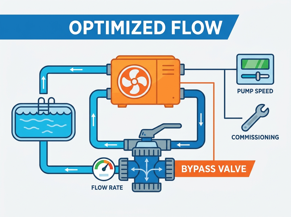
You must translate required GPM into specific RPM settings. A variable speed (VS) pool pump offers precise control. Calculate your Total Dynamic Head (TDH) first. TDH restricts actual flow rates at various pump speeds. A pump running at 1500 RPM delivers different GPM depending on plumbing resistance. Check the pump manufacturer's flow chart carefully. Match the RPM to the heater's minimum GPM threshold.
Add a 10% buffer to this minimum requirement. This buffer ensures consistent operation during minor pressure fluctuations. For example, if your heater requires 40 GPM, and your plumbing has 50 feet of head, you might need to run the pump at 2200 RPM to hit that target. Do not just guess the speed. Use a flow meter installed on the return line to verify the exact water volume moving through the system.
Running a VS pump at ultra-low speeds saves electricity. However, higher RPMs satisfy the mechanical flow switch. You face a conceptual trade-off here. Energy savings compete directly against heating efficiency. Program your daily schedules carefully to balance both needs. Establish a dedicated heating window during the warmest part of the day. Use optimized, higher RPMs during this specific window.
Keep this separate from low-speed filtration cycles. This decision framework maximizes both efficiency and equipment lifespan. We usually set the pump to run at 1200 RPM for basic skimming and filtration. Then we program a specific heating block from 10 AM to 4 PM at 2400 RPM. This guarantees the heater has enough flow to operate when the ambient air temperature is highest, which yields the best COP.
Dirty filters artificially inflate head pressure in your plumbing. Solar heaters and complex water features add system resistance. This reduces actual flow reaching the heating equipment. Establish baseline clean-filter pressures immediately after installation. Set your pump RPMs slightly above the absolute minimum threshold. This accounts for gradual filter loading over the month. It prevents nuisance shut-offs as the filter gets dirty.
Clean your filter cartridges regularly to maintain consistent flow dynamics. If your clean filter pressure is 15 PSI, and it rises to 25 PSI, your flow rate drops significantly. The heater will throw a low-flow error. We see this on service routes every week. The customer thinks the heater is broken, but the filter just needs a deep cleaning. Always check the pressure gauge before adjusting the bypass valves.
Start the system using an exact, methodical sequence. Open all bypass valves fully before turning on the pump. Purge air from the entire filtration loop completely. Verify baseline pump operation before engaging the heater. The internal flow switch must remain in the open position. Verify this status before water begins circulating. Trapped air causes severe mechanical damage to the compressor.
Let the pump run for ten minutes to stabilize pressure. Open the manual air relief valve on top of the filter tank. Wait until a steady stream of water shoots out. This confirms all air pockets are gone. Only then should you flip the breaker for the heating equipment. Rushing this step leads to dry-firing, which voids manufacturer warranties instantly.
The Delta T method ensures perfect hydraulic calibration. It measures the temperature differential across the heat exchanger. Follow these exact steps for accurate measurement.
Measure the water temperature entering the equipment using a digital thermometer.
Measure the water temperature exiting the equipment at the return union.
Gradually throttle the center bypass valve to restrict straight-through flow.
Monitor the temperature difference until it matches the manufacturer's optimal range (typically 2°F to 5°F).
Make slow, incremental valve adjustments. Allow the refrigerant cycle 5 to 10 minutes to stabilize. Take new temperature readings only after this stabilization period. If the Delta T is 8°F, the water is moving too slowly. Open the center valve slightly to increase flow. If the Delta T is 1°F, the water is moving too fast. Close the center valve slightly to force more water through the heat exchanger.
The flow switch relies on a mechanical-to-electrical relationship. The physical paddle signals the main control board. It prevents catastrophic dry-firing of the compressor. Test the mechanical flow switch manually during commissioning. Incrementally lower the VS pump speed by 50 RPM intervals. Wait until the unit registers a flow error code.
Establish this drop-out point as the absolute minimum operational threshold. Ensure your programmed heating speed remains safely above this limit. If the heater drops out at 1600 RPM, set your minimum heating speed to 1800 RPM. This 200 RPM buffer protects the system when the filter gets dirty. Never bypass a faulty flow switch with a jumper wire. This removes the only safety mechanism protecting the titanium coil from melting down.
Diagnostic logic separates flow issues from pressure issues. Proper pool heat pump troubleshooting prevents unnecessary service calls. A flow-related error code requires immediate attention. Differentiate between a genuine lack of water flow and restricted internal flow. Lack of flow triggers the mechanical flow switch. Restricted internal flow causes the refrigerant to overheat rapidly.
Overheating triggers a high-pressure limit switch. Both codes indicate hydraulic problems requiring immediate bypass valve adjustment or filter cleaning. If you see a high-pressure code, the water is likely moving too slowly to remove heat from the refrigerant. The compressor gets too hot and shuts down. If you see a low-flow code, the paddle switch isn't closing at all. Check the pump basket for debris first.
Error Code Type | Primary Cause | Immediate Field Check | Resolution Action |
|---|---|---|---|
Low Flow / No Flow | Insufficient water volume reaching the unit | Check pump basket and skimmers for debris | Clean baskets, increase VS pump RPM |
High Pressure | Water moving too slowly to absorb heat | Check filter pressure gauge | Backwash filter, open bypass center valve |
Low Pressure | Refrigerant leak or extreme cold weather | Check ambient air temperature | Wait for warmer weather or call technician |
Use a systematic checklist for flow degradation. Inspect the skimmer baskets first for leaf buildup. Check the pump impeller for trapped debris or pine needles. Look for suction-side air leaks around the pump lid O-ring. Bubbles in the pump basket indicate air intrusion. Examine your cartridge or sand filter for severe saturation.
A dirty filter severely restricts water movement. Backwash sand filters or chemically clean cartridge elements to restore optimal flow. Sometimes the blockage is inside the heater itself. Scale buildup from poor water chemistry clogs the titanium tubes. If the pool has high calcium hardness, you might need to descale the heat exchanger using a mild acid solution and a submersible pump.
Sometimes bypass adjustment cannot solve persistent flow issues. Establish criteria for re-evaluating your entire plumbing configuration. Mathematical indicators prove when a plumbing upsize becomes necessary. Moving from 1.5-inch to 2-inch pipe drastically increases volume capacity. A complete pump replacement might be required eventually.
The existing pump must support the heating system requirements. Upgrading to a larger variable speed pump solves chronic low-flow error codes permanently. If your equipment pad sits 50 feet away from the pool and uses 1.5-inch pipe, you will fight flow issues forever. The friction loss is simply too high. Trenching in 2-inch or 2.5-inch lines is the only permanent fix for large capacity heaters.
Establish a documented baseline for clean filter pressure and Delta T today.
Schedule a bi-annual hydraulic audit by a certified pool technician to verify flow rates.
Synchronize your variable speed pump schedules with your heating demands to maximize COP.
Mark your optimal bypass valve positions with a permanent marker for easy reference after maintenance.
A: Check the digital display for an active heating status. Feel the water returning to the pool at the jets; it should feel slightly warmer than the bulk pool water. You can also monitor the pressure gauge on your pool filter. A sudden drop in pressure often indicates a flow restriction before the heater. Installing an inline flow meter provides the most accurate visual confirmation of water movement.
A: The ideal Delta T typically falls between 2°F and 5°F. This means the water exiting the heater should be 2 to 5 degrees warmer than the water entering it. Always consult your specific manufacturer's manual, as exact ranges vary slightly between different models and capacities. Measuring this requires a precise digital thermometer at the inlet and outlet unions.
A: The center diverter valve should be partially closed during normal operation. This creates backpressure, forcing the correct amount of water through the heater. The inlet and outlet valves should remain fully open. Adjust the center valve in small increments until you achieve the correct Delta T. Mark this position with a marker for future reference.
A: Low pump speeds often fail to meet the heater's minimum GPM requirement. This lack of flow triggers the internal flow switch, shutting down the compressor to prevent damage. You must program a higher RPM setting during dedicated heating cycles to satisfy the flow switch. Separate your low-speed filtration schedules from your high-speed heating schedules.
A: Yes, excessive water flow causes severe problems. It prevents the water from absorbing heat efficiently, lowering your COP. Over time, pushing water too fast causes erosive wear on the internal titanium heat exchanger. It can also cause internal pressure imbalances within the refrigerant cycle, leading to premature compressor failure. Always use a bypass manifold to throttle excessive flow.
A: Locate the manufacturer's data plate, usually riveted to the side or back panel of the unit. This plate lists the model number, serial number, and minimum/maximum GPM requirements. If the plate is unreadable, search the model number online to find archived installation manuals. You can also contact the manufacturer's technical support line with the serial number for exact specifications.


