


Views: 0 Author: Site Editor Publish Time: 2026-10-24 Origin: Site


Transitioning from traditional direct expansion air conditioning to hydronic cooling requires a fundamental shift in how you manage moisture within the building envelope. When chilled water circulates through a building, any surface temperature dropping below the ambient dew point generates condensation. Failure to manage this moisture leads to structural water damage, biological growth, and degraded indoor air quality. These failures turn an energy-efficient upgrade into a costly liability. In regions with consistently high ambient dew points, unmanaged humidity drastically increases system run times, inflates energy costs, and compromises occupant comfort. Successfully deploying hydronic cooling requires precise control over supply water temperatures, accurate dew point tracking, and robust condensate drainage infrastructure. This guide provides the technical evaluation criteria for configuring emitters and piping networks to safely handle latent cooling loads using an air-to-water heat pump.
Dew Point dictates system design: Supply water temperatures must be dynamically controlled via active dew point sensors to prevent unintended condensation on uninsulated surfaces or radiant slabs.
Latent cooling requires purpose-built hardware: Not all hydronic emitters can handle cooling. Utilizing fan coil units with heat pumps requires verified condensate pans, properly trapped drain lines, and insulated piping.
Drainage compliance is non-negotiable: Condensate must be routed to acceptable discharge points (e.g., dedicated exterior drains, floor drains, or internal plumbing tie-ins) to meet commercial and residential building codes.
Bypass factors impact dehumidification: The physical design of the fan coil (fin spacing, coil depth) determines its Apparatus Dew Point (ADP) and its effectiveness at removing humidity versus just lowering sensible temperature.
Establishing the baseline requirement for a cooling system comes down to managing two distinct thermal loads. The system must handle sensible heat, which dictates the temperature you read on a thermostat, and latent heat, which represents the moisture suspended in the air. You cannot achieve true indoor comfort without addressing both. High humidity makes spaces feel clammy and warm, even if the dry-bulb temperature is low. Hydronic systems use water as the primary heat transfer medium because water possesses a high specific heat capacity, making it highly efficient for moving thermal energy across long distances. However, pumping cold water through a building creates massive condensing surfaces wherever the pipe or emitter temperature falls below the room's dew point.
As air cools, it loses its physical capacity to hold water vapor. This moisture must condense on cold coils and be safely drained away from the living space. Radiant floor and ceiling systems have strict limitations regarding latent heat. They only provide sensible cooling. If you use radiant surfaces for cooling, the supply water must remain above the dew point at all times. Pushing flow temperatures down to 17°C (62°F) or lower without active dew point monitoring invites severe slab condensation. Sweating floors destroy hardwood, create slip hazards on tile, and promote mold growth under carpets. You cannot use radiant slabs to dehumidify a building.
To actively remove moisture, you need purpose-built emitters. Capable of latent cooling, fan coil units with heat pumps allow supply water to drop to 7°C (45°F). This low temperature actively condenses and removes moisture from the air stream. The internal fan forces warm, humid room air across the chilled finned-tube heat exchanger. The air cools rapidly, sheds its moisture into a dedicated drain pan, and returns to the room cold and dry. This process mimics traditional air conditioning but uses chilled water instead of direct refrigerant.
The entire process relies on a reversing valve located inside the outdoor unit. This valve shifts the flow of hot discharge gas from the compressor, changing the refrigerant cycle to produce chilled water instead of hot water. The outdoor coil acts as the condenser, rejecting building heat into the outside air. The indoor brazed plate heat exchanger acts as the evaporator, chilling the water loop. Buffer tanks play a massive role during this cycle. They act as thermal batteries, storing chilled water to prevent the compressor from cycling on and off rapidly during low-load conditions. Short-cycling destroys compressors and ruins dehumidification efficiency because the indoor coil never stays cold long enough to extract meaningful moisture. A properly sized buffer tank ensures stable chilled water delivery and extends the lifespan of the mechanical components.
Environmental monitoring directly translates to system safety and efficiency. Understanding the Apparatus Dew Point (ADP) is essential for effective moisture removal. ADP represents the effective average surface temperature of the cooling coil. The psychrometric chart maps the exact relationship between dry-bulb temperature, wet-bulb temperature, and humidity ratio. It shows precisely when water vapor will turn into liquid condensate. Dehumidification only occurs when the coil surface temperature strictly falls below the entering air's dew point. If room air is 24°C (75°F) with 50% relative humidity, the dew point is roughly 13°C (55°F). To dehumidify that space, the coil must operate well below 13°C.
Air velocity and coil design dictate moisture removal rates. The Contact Factor measures the percentage of air that actually touches the cold coil fins. Conversely, the Bypass Factor measures the air passing through the coil untreated. Coil design heavily influences these metrics. Tighter fin spacing and deeper coils increase the Contact Factor but require more fan power to overcome static pressure. Wider spacing reduces air resistance but increases the Bypass Factor. High bypass means humid air slips through the unit without shedding its moisture. High fan speeds increase sensible cooling but drastically reduce latent moisture removal. This trade-off negatively impacts comfort in high-humidity zones. Installers must balance fan speed and water temperature based on regional climate data.
Coil Configuration | Fin Spacing | Bypass Factor Impact | Dehumidification Capability |
|---|---|---|---|
2-Row Coil | Wide (10-12 FPI) | High (20% - 30%) | Poor. Best for sensible cooling only. |
3-Row Coil | Medium (12-14 FPI) | Moderate (10% - 15%) | Good. Standard for residential latent loads. |
4-Row Coil | Tight (14+ FPI) | Low (Under 5%) | Excellent. Required for high-humidity coastal zones. |
Active dew point tracking requires indoor humidity and temperature sensors across multiple levels of the building. Sensor placement dictates the accuracy of the entire system. Never place humidity sensors near supply air grilles, in direct sunlight, or adjacent to bathrooms. Multi-story buildings face significant humidity stratification. Basement equipment locations and second-story living spaces experience uneven humidity pooling. Basements are naturally cooler and trap dampness. Upper floors experience higher sensible heat loads from roof exposure and different moisture profiles. Zoned sensor data is mandatory to capture these variations accurately.
The master controller uses this real-time data to dynamically adjust the leaving water temperature. It averages the inputs or targets the worst-case zone, modulating the compressor speed and mixing valves accordingly. This prevents condensation on distribution piping and ensures optimal dehumidification cycles. If the indoor dew point rises, the system lowers the water temperature to increase latent cooling capacity, provided the piping infrastructure is properly insulated to handle the colder fluid.
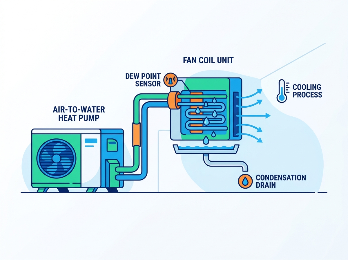
Standard hydronic radiators cannot handle chilled water. They rely on natural convection, have small surface areas, and are designed to run at high temperatures. Pumping 7°C (45°F) water through a cast iron or steel panel radiator causes instant surface sweating. Water will pool on the floor within minutes, causing severe property damage. Purpose-built cooling emitters are required to manage latent loads safely and effectively.
Mandatory hardware features for latent cooling include several specific components. First, condensate drain pans are critical. These must be sloped at a minimum of 1% toward the drain port, constructed from corrosion-resistant materials like stainless steel or heavy-duty polymer, and properly sized to catch blow-off from the coil. A flat pan holds stagnant water, leading to algae growth, foul odors, and eventual overflow. Second, hydrophilic coil coatings are essential. This microscopic treatment reduces the surface tension of water on the aluminum fins. Instead of forming large droplets that bridge the gap between fins and restrict airflow, water sheets off rapidly. This keeps the coil clear, maintains static pressure, and improves heat transfer efficiency.
Variable speed ECM motors provide precise airflow control. Older AC motors only run at fixed speeds, which limits dehumidification control. ECMs ramp down to very low RPMs based on the thermostat demand. Slowing the air increases its dwell time across the cold coil. This maximizes moisture removal without overcooling the room. Continuous low-speed fan operation improves overall air mixing and prevents humidity pockets from forming in corners or behind furniture.
Sizing equipment for high humidity environments requires careful calculation. You must separate the sensible load from the latent load during the design phase. Total capacity must account for high latent loads, especially in coastal climates where 75% relative humidity and high outdoor dew points are common. In these areas, latent loads can exceed 30% of the total cooling requirement. Undersizing the coil leads to inadequate dehumidification, leaving the space feeling sticky. Oversizing leads to short-cycling. An oversized unit cools the air too quickly and shuts off before it has time to remove sufficient moisture, resulting in cold, clammy indoor conditions.
The physical routing of condensed water prevents severe property damage. Drainage compliance is non-negotiable for both residential and commercial installations. Gravity remains the most reliable drainage method. Drain lines must maintain a continuous downward slope. This ensures water flows freely and prevents stagnation. Stagnant water breeds algae and bacterial slime, which quickly clogs the pipe and causes catastrophic overflows inside the building envelope.
Acceptable discharge points include dedicated dry wells outside the building, graded away from the foundation. You can also route lines near an approved floor drain or use indirect connections to sanitary sewers with proper air gaps. Designated HVAC condensate drains tied into the building's plumbing system are standard practice in new construction. Always verify that the termination point can handle the volume of water produced during peak cooling days, which can amount to several gallons per hour for a large system.
Unacceptable discharge points create hazards and structural risks. Never discharge directly onto walkways, as this creates a severe slip hazard due to algae growth and standing water. Discharging into crawlspaces causes structural moisture damage, rotting wood framing, and inviting termite infestations. Routing directly into plumbing vents without traps allows dangerous sewer gases to enter the building envelope, creating severe health risks.
Drainage Component | Function and Requirement | Failure Consequence |
|---|---|---|
P-Trap (Draw-Through) | Overcomes negative cabinet pressure to allow drainage. | Air pulls up the pipe; water cannot drain; pan overflows. |
P-Trap (Blow-Through) | Prevents conditioned air from escaping the drain line. | Energy loss; whistling noises; potential moisture blowing out. |
Cleanout Tee | Provides access to clear algae and sludge blockages. | Requires cutting the pipe to clear clogs, increasing maintenance time. |
Air Gap | Prevents sewer backup from contaminating the HVAC system. | Raw sewage backs up into the drain pan during plumbing failures. |
Traps, vents, and cleanouts maintain proper flow and system hygiene. P-traps are mandatory for draw-through fan configurations. In a draw-through unit, the fan pulls air across the coil, creating negative pressure inside the cabinet. Without a properly sized P-trap, this negative pressure pulls outside air up the drain pipe. The rising air prevents water from draining out, causing the pan to overflow. Positive pressure coils push air across the fins. They still require traps to prevent conditioned air from escaping. Always install a cleanout tee before the trap to allow maintenance personnel to clear blockages easily with a wire brush or compressed air.
Condensate pumps introduce mechanical complexity but are necessary when gravity drainage is impossible. Basement installations or retrofitted second-story units often require them. These pumps have a specific lift capacity, known as head pressure. You must calculate the vertical and horizontal distance to the discharge point to select the right pump. Mandatory safety features include overflow cutoff switches. The switch must be wired in series with the thermostat or unit control board to shut down the cooling call if the pump fails, preventing indoor flooding.
Adapting residential concepts for large-scale applications requires strict oversight and robust engineering. A commercial air-to-water heat pump handles massive latent loads across multi-tenant spaces. Large buildings utilize complex piping networks. Chilled water lines often run through unconditioned ceiling plenums, mechanical shafts, or parking garages. These spaces experience high heat and humidity, making condensation management the highest priority for the mechanical contractor.
Chilled water pipe insulation is critical. Strict requirements mandate closed-cell elastomeric foam insulation on all supply and return piping. Fiberglass insulation is completely unacceptable for chilled water. It lacks a built-in vapor barrier, absorbs moisture, loses its thermal resistance, and promotes mold. Vapor barriers must be flawless and continuous. Every joint, elbow, and valve must be sealed with specialized contact adhesive. Pipe hangers require rigid polyurethane insulation inserts with metal shields. If a metal hanger touches the bare pipe, it creates a thermal bridge. Condensation will form on the hanger and drip onto the ceiling tiles below, causing damage and potential electrical hazards.
Building Management System (BMS) integration provides centralized control and optimizes energy use. The system monitors dew points across different building zones to manage varying latent loads. It adjusts the chilled water setpoint based on occupancy schedules, internal heat gains, and weather forecasts. During peak humidity events, the BMS lowers the water temperature to maximize latent cooling. During dry periods, it raises the temperature to save compressor energy and improve the Coefficient of Performance (COP). Effective zoning strategies mix radiant cooling in low-load areas like lobbies with ducted fan coils in high-load areas like crowded conference rooms.
Balancing upfront installation costs against long-term performance dictates the success of commercial hydronic cooling. The higher installation cost of insulated piping and drainage infrastructure pays off rapidly. It delivers operational savings and decarbonization benefits through a unified commercial plant. These systems eliminate fossil fuel combustion on site. They also drastically reduce the total refrigerant volume compared to variable refrigerant flow systems. Water acts as the primary transport fluid, confining the refrigerant to the outdoor plant. This simplifies maintenance, reduces leak risks, and ensures compliance with strict environmental regulations regarding global warming potential.
Take the following steps to ensure a successful installation:
Audit your current or proposed piping infrastructure to verify strict closed-cell insulation integrity and continuous vapor barriers.
Verify the specific latent capacity and Apparatus Dew Point of your selected fan coils against your regional climate data.
Consult a mechanical engineer to calculate the exact dew point requirements and buffer tank sizing for your specific zone.
Inspect all planned condensate drain routes to ensure full compliance with local building codes and proper trap sizing.
Install multi-zone humidity sensors to provide accurate, stratified data to the master controller for dynamic water temperature adjustment.
A: No, 75% indoor relative humidity is too high. It indicates the system is short-cycling, the supply water temperature is above the dew point, or the fan speed is too high for adequate dehumidification. In multi-story units, it often points to poor airflow reaching upper levels. You should target 45% to 55% relative humidity for optimal indoor comfort and to prevent biological growth.
A: You must keep the flow temperature at least 1-2°C above the calculated room dew point. Dropping supply temperatures to 17°C (62°F) or below without active dew point sensors is dangerous. It invites severe slab condensation and will permanently damage your flooring. Always use a mixing valve controlled by a dew point sensor.
A: Uninsulated pipes will immediately condense ambient moisture from the air. This leads to dripping water, heavily damaged drywall, mold growth, and the eventual corrosion of pipe fittings and valves. Closed-cell elastomeric insulation with a sealed vapor barrier is mandatory for all chilled water lines.
A: Acceptable locations include an exterior grade directed away from the foundation, near an approved floor drain, or into an indirect waste receptor with an air gap. You must always ensure local code compliance. Never discharge onto walkways or directly into crawlspaces.
A: No. Standard hot water radiators lack condensate drain pans and proper insulation. Pumping chilled water through them will cause uncontrolled surface condensation. This leads to severe water damage on your floors and walls within minutes of operation. You must use purpose-built cooling emitters.
A: The bypass factor is the percentage of air that passes through the cooling coil without touching the fins. This air remains uncooled and undehumidified. A high bypass factor reduces the unit's ability to manage latent loads and remove humidity from the room, resulting in poor comfort.


