


Views: 0 Author: Site Editor Publish Time: 2026-08-20 Origin: Site


Traditional fossil-fuel boilers operate on a high-temperature paradigm, pushing water at 70°C to 80°C through the distribution circuit. Modern hydronic heating relies on entirely different thermodynamic realities. Retrofitting a new generation heating source onto legacy distribution systems built for high temperatures guarantees underperformance. The core technical problem always comes down to flow temperature. Failing to design a system for low flow temperatures (35°C to 45°C) forces the compressor to work harder. This severely degrades the Coefficient of Performance (COP), increases operational costs, and causes premature equipment wear.
To ensure a heat pump operates at peak seasonal efficiency, you need a ground-up design approach. This covers exact room-by-room heat loss calculations, proper emitter sizing, hydraulic balancing, and specific control strategies. Moving away from historical rules of thumb and embracing precise engineering calculations is the only way to achieve reliable, efficient low-temperature heating.
Efficiency is dictated by flow temperature: Every 1°C reduction in flow temperature can improve heat pump efficiency by 1.5% to 2.5%.
Precision calculations are non-negotiable: Rule-of-thumb sizing leads to short-cycling or inadequate heating; exact room-by-room heat loss calculations (e.g., CIBSE or ACCA Manual J standards) are required.
Emitter surface area must scale up: Low-temperature systems require significantly larger heat transfer surfaces, making underfloor heating or oversized radiators mandatory.
Hydraulic flow rates differ from boilers: Heat pumps operate on lower temperature differentials (ΔT of 5°C–7°C), requiring larger pipework to handle increased mass flow rates without excessive pressure drops.
DHW require separate design considerations: Integrating Domestic Hot Water (DHW) requires dedicated high-surface-area coil cylinders to prevent system short-cycling and maintain COP.
In modern HVAC design, "low temperature" heating refers strictly to flow temperatures between 35°C and 45°C. This contrasts sharply with medium-temperature (50°C to 60°C) and high-temperature (70°C+) systems. The success of any installation hinges on keeping the system operating within this lower temperature band for as much of the heating season as possible.
There is a direct, inverse relationship between the required flow temperature and the Coefficient of Performance (COP). The COP measures the ratio of heat output to electrical energy input. When you demand higher temperatures from the compressor, the refrigerant cycle must work against a higher pressure differential. This consumes more electrical energy for the same thermal output.
Consider a standard residential unit. It might achieve a COP of 4.5 at a flow temperature of 35°C. This means it produces 4.5 units of heat for every 1 unit of electricity consumed. If the flow temperature requirement increases to 55°C to satisfy undersized radiators, the COP might drop to 2.5. The objective of system design is to achieve the lowest possible flow temperature that still meets the building's peak heat load on the design day. The design day is the coldest statistically probable day of the year for that specific geographic location.
Flow Temperature (°C) | Typical COP | Electrical Input for 10kW Output (kW) | System Efficiency Impact |
|---|---|---|---|
35°C | 4.5 | 2.22 | Optimal |
45°C | 3.5 | 2.85 | Good |
55°C | 2.5 | 4.00 | Poor |
Designing for 35°C flow temperatures requires massive heat emitter surface areas, which is why underfloor heating is heavily favored. When retrofitting older properties, achieving 35°C is often impossible without stripping the building back to its brickwork. In these cases, engineers aim for 45°C or 50°C, accepting a lower COP in exchange for practical installation feasibility.
Historical boiler sizing methods relied heavily on rules of thumb. Installers would estimate 50 watts per cubic meter or simply look at the size of the existing boiler and match it. This frequently resulted in systems oversized by 20% to 50%. A gas boiler can cycle on and off to manage this excess capacity relatively well. An oversized compressor, however, will short-cycle. Short-cycling drastically reduces efficiency, prevents the system from reaching steady-state operation, and accelerates component degradation.
Accurate heat loss calculations require assessing several key variables. You cannot guess these numbers. Engineers must determine the exact U-values of the building envelope. This includes measuring the thermal transmittance of the walls, roof, floors, and glazing. Air change rates, factoring in both natural infiltration through drafts and controlled ventilation, must be calculated. Finally, the required internal design temperatures for each room dictate the baseline requirement. A bathroom typically requires 22°C, while a hallway might only need 18°C.
Measure all room dimensions to calculate total volume and exposed surface areas.
Identify the construction materials to assign accurate U-values to walls, floors, and ceilings.
Determine the glazing type (single, double, triple) and frame material to calculate window heat loss.
Estimate the air infiltration rate based on the age and airtightness of the property.
Select the external design temperature based on local meteorological data.
Calculate the total wattage required to maintain the target internal temperature for each specific room.
Establishing the Design Delta T (ΔT) involves calculating the difference between the target indoor temperature and the local external design temperature. If the outside design temperature is -3°C and the living room target is 21°C, the Design ΔT is 24°C. This calculation establishes the maximum required heat load in kilowatts (kW) for each specific room. You use this exact kW figure to select the heat emitters, ensuring they can deliver adequate warmth without relying on elevated flow temperatures.
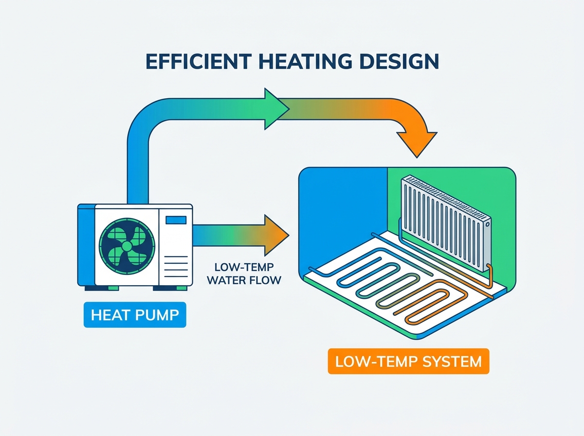
Because low-temperature systems operate with cooler water, they require significantly larger surface areas to transfer the same amount of heat into a room. You cannot push 40°C water through a standard single-panel radiator and expect it to heat a room designed for 75°C water.
Underfloor heating is the gold standard for low-temperature hydronics. It turns the entire floor into a massive heat emitter, allowing for flow temperatures as low as 35°C. When designing UFH, you must consider screed depth, pipe spacing, and the resulting response times. Closer pipe spacing (e.g., 100mm or 150mm centers) generally allows for lower flow temperatures and higher heat outputs per square meter. The thermal conductivity of the floor finish also plays a massive role. Tile and stone transfer heat excellently, while thick carpets act as insulators, forcing the system to run hotter to push the heat through.
If UFH is not feasible, existing radiators must be evaluated and likely replaced. Radiators for low-temperature systems are sized using a ΔT of 30 or ΔT of 20, rather than the traditional boiler ΔT of 50. This necessitates installing double or triple-panel convector radiators (e.g., K2 or K3 types). The Log Mean Temperature Difference (LMTD) dictates the actual heat output at these lower temperatures, requiring careful calculation.
Radiator Type | Output at ΔT 50 (Boiler) | Output at ΔT 30 (Heat Pump) | Physical Size Increase Required |
|---|---|---|---|
Type 11 (Single Panel) | 1000W | ~500W | 2.0x larger |
Type 22 (Double Panel) | 1800W | ~900W | 2.0x larger |
Type 33 (Triple Panel) | 2500W | ~1250W | 2.0x larger |
When sizing these radiators, you must look at the manufacturer's data tables for the specific flow and return temperatures you intend to use. A radiator that outputs 1500W at 75/65°C might only output 600W at 45/40°C. You must physically accommodate these larger units on the walls, which often requires moving pipework.
Fan Coil Units (FCUs) and smart radiators offer a middle ground. These active emitters use small, quiet fans to increase convective heat transfer. They blow air across a heat exchanger coil, stripping the heat away much faster than natural convection. They are highly effective in retrofit scenarios where wall space is limited. An FCU can deliver the same heat output as a massive K3 radiator while taking up a fraction of the space, allowing for lower flow temperatures without dominating the room visually.
The hydraulic requirements for a low-temperature system differ significantly from those of a traditional boiler. Low-temperature systems operate on a smaller temperature differential across the emitter. A boiler typically operates with an 11°C to 20°C drop between the flow and return pipes. A modern hydronic system operates on a ΔT of 5°C to 7°C. To deliver the same amount of heat energy with a smaller temperature drop, the mass flow rate of the water must be significantly higher.
Upgrading pipe diameters is almost always necessary in retrofit scenarios. Moving from 15mm to 22mm or 28mm copper or PEX prevents high fluid velocity. Excessive velocity causes system noise, erosion corrosion inside copper fittings, and can easily exceed the circulating pump's head capacity. If the pump cannot push the required volume of water through restrictive micro-bore pipework, the system will trip on high-pressure faults or fail to deliver heat to the furthest emitters.
Pipe Diameter (Copper) | Max Recommended Flow Rate (L/sec) | Max Heat Carrying Capacity at ΔT 5°C |
|---|---|---|
15mm | 0.15 | ~3.1 kW |
22mm | 0.35 | ~7.3 kW |
28mm | 0.60 | ~12.5 kW |
If antifreeze or glycol is added to the system to prevent freezing in monobloc units, it affects the fluid's physical properties. Propylene glycol lowers the specific heat capacity of the fluid and increases its kinematic viscosity. This means the fluid carries less heat per liter and is harder to pump. You must upsize the circulating pumps and adjust the emitter sizing calculations to account for the reduced heat transfer efficiency of the glycol mixture.
Plate heat exchangers are highly vulnerable to debris and oxygen-induced corrosion. The internal channels are incredibly narrow and block easily. Installing high-efficiency microbubble deaerators and magnetic dirt separators on the return pipework is mandatory to protect the equipment. Buffer tanks or low-loss headers are frequently used to decouple the primary circuit from the secondary heating circuit. This hydraulic separation ensures the primary pump maintains minimum flow rates across the heat exchanger even if all the thermostatic radiator valves (TRVs) in the house close simultaneously.
Integrating Domestic Hot Water (DHW) presents a specific design challenge. Space heating operates efficiently at 35°C to 45°C, but DHW requires storage at 55°C to 60°C to prevent Legionella bacteria growth. You are asking a machine designed for low temperatures to produce high temperatures.
Standard hot water cylinders are completely incompatible with low-temperature heat sources. Standard cylinders have small internal coils designed for 80°C boiler water. If you pump 55°C water through a standard coil, the heat transfer is so slow that the primary circuit returns to the compressor too hot, causing it to shut down before the cylinder is fully heated. Heat-pump-specific cylinders feature oversized internal heat exchanger coils. A typical residential system requires a minimum coil surface area of 3.0 m². This massive surface area ensures rapid heat transfer without triggering high-refrigerant-pressure faults.
The system utilizes 3-port or twin 2-port diverting valves to dynamically prioritize DHW production over space heating. When the cylinder thermostat calls for heat, the diverter valve shifts, directing the full output of the compressor into the cylinder coil. The flow temperature ramps up to 55°C or 60°C. Once the cylinder is satisfied, the valve shifts back, the flow temperature drops back to 35°C, and space heating resumes. This priority switching ensures the cylinder recovers quickly without requiring a secondary heat source.
Weather compensation controls dynamically adjust the flow temperature based on real-time outdoor temperatures. This is the brain of a high-efficiency system. On milder winter days, the system lowers the flow temperature, maximizing the COP. As the outdoor temperature drops, the flow temperature increases along a predefined curve to meet the higher heat load of the building.
Setting the correct weather compensation curve requires understanding the building's thermal response. If the curve is too steep, the system runs too hot, wasting energy. If the curve is too shallow, the building will not reach the target temperature during cold snaps. Installers must fine-tune this curve during the first year of operation based on client feedback and actual performance data.
While zoning allows for individual room temperature control, over-zoning can restrict flow and cause short-cycling. If a house has 15 micro-zones controlled by smart thermostats, and 14 of them close, the compressor is left trying to push its minimum output into a single radiator. This causes rapid temperature spikes and immediate shutdowns. Implementing open-loop zones (areas without TRVs, usually hallways or bathrooms) or strategically placed automatic bypass valves ensures the system always has an adequate volume of water to heat, maintaining stable operation.
Installing too many TRVs or smart thermostats that shut off simultaneously starves the primary circuit of flow. Mitigate this by using an open-loop zone or a correctly sized buffer vessel. A buffer vessel acts as a thermal battery, absorbing excess heat when zones close and providing a stable return temperature to the compressor.
Insufficient system volume can also fail to provide the thermal energy required for the defrost cycle. Air source units extract heat from the outside air, causing condensation to freeze on the evaporator coil. To clear this ice, the system reverses its cycle, pulling heat from the indoor heating circuit to melt the ice outside. If the indoor pipework does not contain enough water volume, the defrost cycle will fail, or the indoor radiators will turn freezing cold. Ensure minimum system volume requirements are met, utilizing a volumetric buffer if necessary.
Poor hydraulic balancing leads to uneven heating and massive inefficiency. If the water takes the path of least resistance through the closest radiators, the furthest rooms will remain cold. The user will then turn up the main thermostat, forcing the compressor to run hotter and longer, destroying the COP. Mandate strict commissioning protocols. This includes setting the lockshield valves on every radiator to achieve the correct temperature drop across the emitter, verifying flow rates on UFH manifolds, and ensuring the main circulating pump is set to the correct proportional pressure curve.
A low-temperature heating system requires exact engineering, precise hydraulic balancing, and a complete departure from legacy boiler installation habits. The efficiency of the heat source is entirely dependent on the distribution network attached to it.
Commission an independent, room-by-room heat loss calculation before selecting any equipment.
Review the proposed hydraulic schematic to verify pipe sizing and buffer tank integration.
Ensure all heat emitters are sized for a maximum flow temperature of 45°C.
Demand a full hydraulic balancing report during the final commissioning handover.
A: The ideal flow temperature is between 35°C and 45°C. Operating within this low-temperature range maximizes the Coefficient of Performance (COP), significantly reducing electrical energy consumption and lowering running costs compared to higher temperature settings.
A: While technically possible, existing radiators usually require upgrading. Because the system operates at lower flow temperatures, legacy radiators often need to be replaced with larger double or triple-panel models to deliver adequate heat to the room.
A: Weather compensation dynamically adjusts the system's flow temperature based on the outdoor temperature. On milder days, it lowers the flow temperature, which significantly improves the COP and reduces energy usage without sacrificing indoor comfort.
A: They deliver heat using a smaller temperature differential (ΔT) across the emitters. To transfer the same amount of thermal energy as a high-temperature boiler, a larger volume of water must circulate through the system, necessitating higher flow rates and larger pipes.
A: A buffer tank is often required to maintain minimum flow rates, prevent short-cycling when radiator valves close, and provide the necessary thermal mass for the defrost cycle. It decouples the primary circuit from the secondary heating zones.


